
Reading the LEONA-B375K single-line diagram: 3 x 125 kW, a 400 kVA transformer and one-cluster-one-management
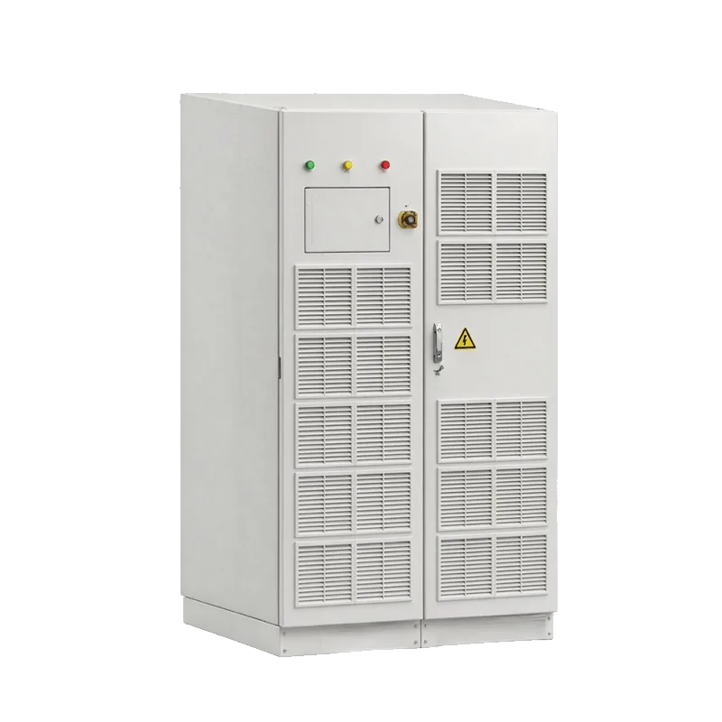
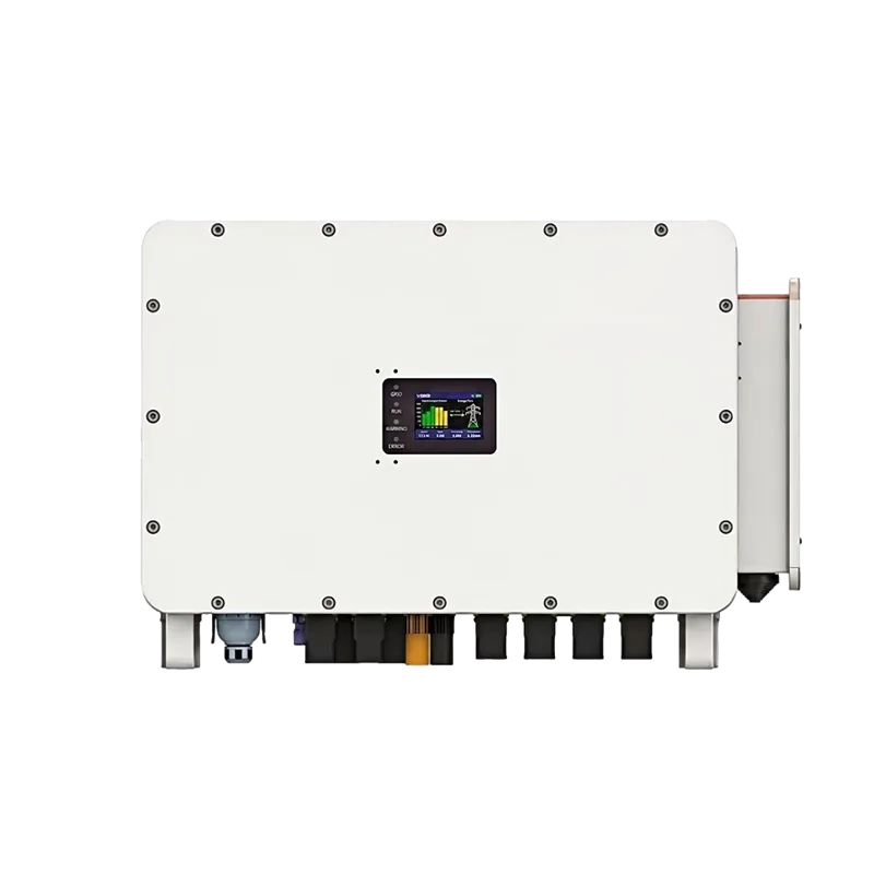
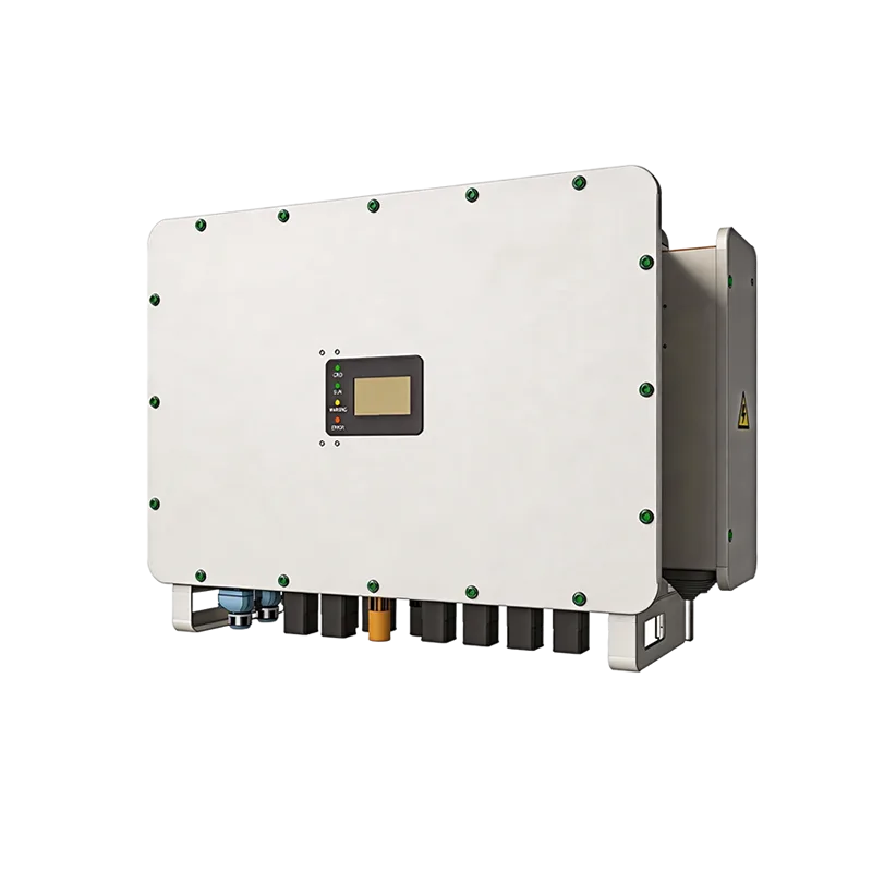
Summary: The LEONA-B375K IP54 cabinet integrates three SP125HCPS 125 kW converters, a 400 kVA isolation transformer, an STS, DC busbars, the EMS and every breaker in one enclosure. The system is rated 375 kW at 400 V/50 Hz with transfer below 20 ms. The point of the single-line diagram is not summing power ratings but seeing where battery clusters, breaker numbers and critical loads attach to the bus.
The LEONA-B375K IP54 cabinet integrates three SP125HCPS 125 kW converters, a 400 kVA isolation transformer, an STS, DC busbars, the EMS and every breaker in one enclosure. The system is rated 375 kW at 400 V/50 Hz with transfer below 20 ms. The point of the single-line diagram is not summing power ratings but seeing where battery clusters, breaker numbers and critical loads attach to the bus.
Power path and critical load position
PCS-1 to PCS-3 each deliver 125 kW DC/AC into the 400 V AC bus, then through transformer TR and the STS to the grid connection point. QF1, the load breaker, sits between TR and the STS, so critical loads are fed from that section; QF2 and SPD1 sit on the STS output side. This arrangement keeps critical loads energised by the PCS voltage source after the grid opens, and is the physical basis of the sub-20 ms transfer.
Battery clusters and DC protection numbering
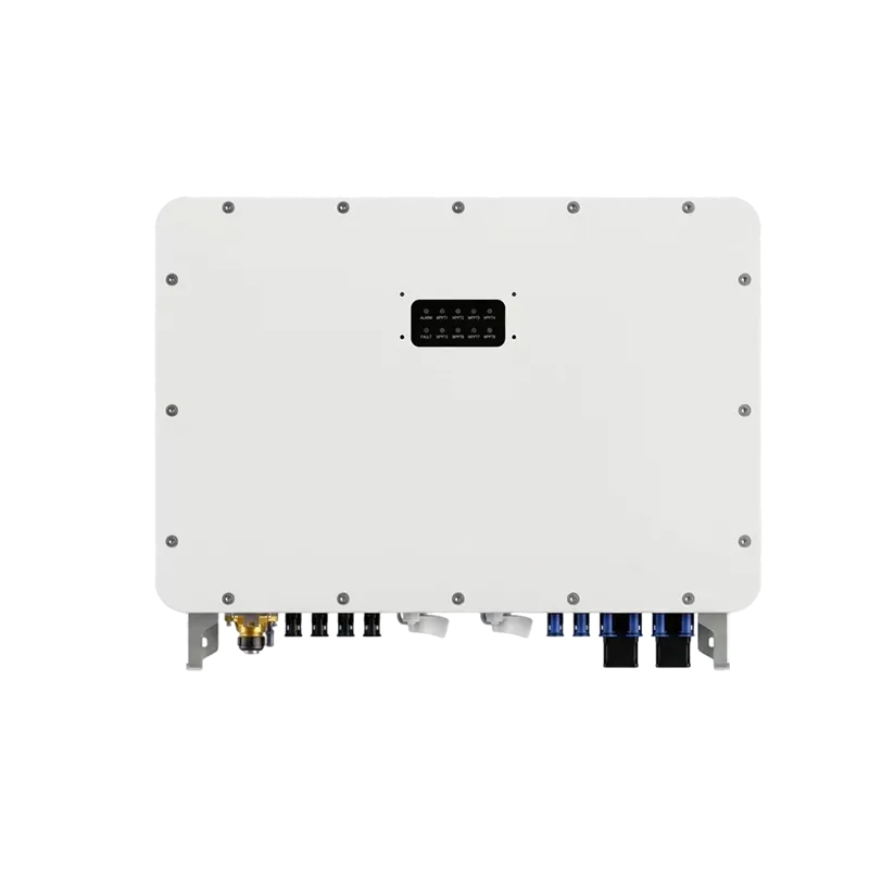
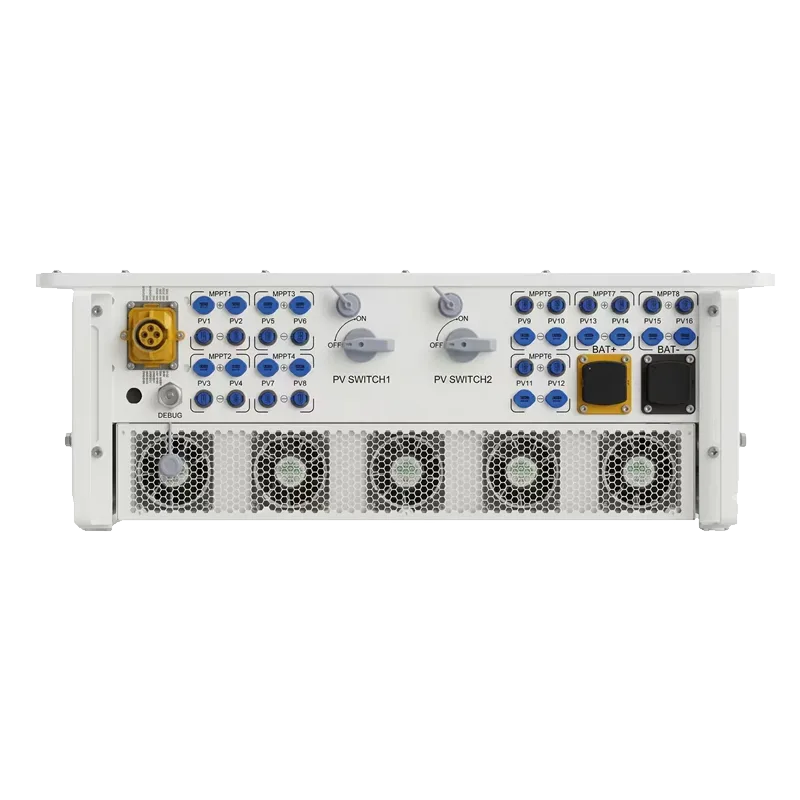
One-cluster-one-management assigns three LFP clusters with independent BMS, each DC 680-900 V / 200 A, through QF3, QF4 and QF5 to the internal DC busbar. Each PCS controls its own cluster, avoiding inter-cluster circulating current. Three reserved SP200HAPV MPPT units of 200 kW each connect through QF6-QF8, fuses FU1-FU3 and surge devices SPD2-SPD4 to the same busbar, providing DC-coupled PV expansion. The QF numbering and the SPD/FU mapping should be written into the acceptance checklist when the drawing is frozen.
EMS communications and selection limits
The EMS reads battery clusters over BMS_CAN, drives the three converters over PCS_485, collects reserved PV data over MPPT_485 and reads the grid meter over METER_485. If site battery voltage falls outside 680-900 V, continuous power exceeds 375 kW, or the transformer must be placed outside the cabinet, do not reuse this diagram directly: move to the B750K split solution or a multi-unit paralleling design and recheck short-circuit protection and earthing.
Frequently asked questions
What does one-cluster-one-management solve?
Each PCS controls one battery cluster independently, preventing circulating currents and SOC drift between paralleled clusters, and allowing a single cluster to be serviced while the system stays online.
Can PV be added to a B375K later?
The diagram reserves three MPPT inputs (QF6-QF8, fuses and SPDs). Adding SP200HAPV units enables DC-coupled PV charging, subject to the battery charge-current limit and the EMS dispatch strategy.
Related equipment and guides
SP750H54PSTD · SP135HAPSS · SP125HCPS · SP200/150HAPV · All technical guides · Product catalogue。
FAQ
What does one-cluster-one-management solve?
Each PCS controls one battery cluster independently, preventing circulating currents and SOC drift between paralleled clusters, and allowing a single cluster to be serviced while the system stays online.
Can PV be added to a B375K later?
The diagram reserves three MPPT inputs (QF6-QF8, fuses and SPDs). Adding SP200HAPV units enables DC-coupled PV charging, subject to the battery charge-current limit and the EMS dispatch strategy.