
LEONA-B375K field wiring and acceptance: breakers, SPDs, earthing and EMS links

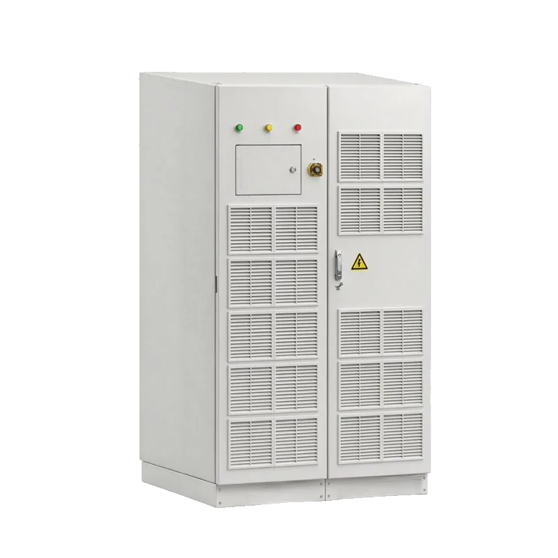
Summary: The LEONA-B375K single-line diagram (V1.0, 2026-10-19) integrates three SP125HCPS converters, a 400 kVA isolation transformer, an STS, DC busbars, the EMS and breakers QF1-QF8 in one IP54 cabinet. Site work is not redesign but checking every breaker number, surge device, earth bar and the four EMS communication paths against the drawing, then verifying sub-20 ms transfer with waveform records.
The LEONA-B375K single-line diagram (V1.0, 2026-10-19) integrates three SP125HCPS converters, a 400 kVA isolation transformer, an STS, DC busbars, the EMS and breakers QF1-QF8 in one IP54 cabinet. Site work is not redesign but checking every breaker number, surge device, earth bar and the four EMS communication paths against the drawing, then verifying sub-20 ms transfer with waveform records.
DC numbering and protection
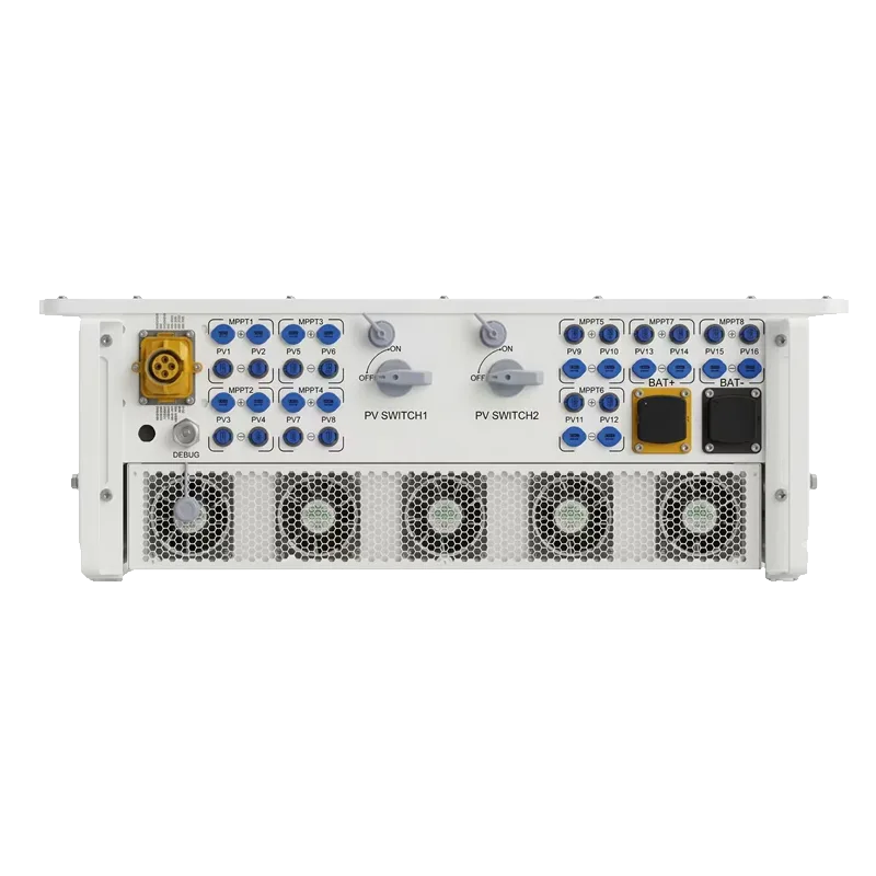
QF1 is the load breaker on the bus between transformer TR and the STS; QF2 and SPD1 sit on the STS output side; QF3-QF5 are the DC breakers for three battery clusters (DC 680-900 V / 200 A, each with its own BMS); QF6-QF8 are reserved MPPT DC breakers. MPPT inputs pass through fuses FU1-FU3 and surge devices SPD2-SPD4 before reaching the internal DC busbar. Check every number during acceptance, and in particular confirm QF6-QF8 are open and tagged when no MPPT is installed.
Cable sizes, earthing and the AC path
The port tables for the same family recommend 90 mm2 for battery cables, 50 mm2 for loads, 5 mm2 for PV and 10 mm2 for PE, with OT240-12 lugs for grid/genset connections (B750K/H135K port definitions; for a B375K project the final drawing and cabinet terminals govern). The AC path is 400 V bus to isolation transformer TR to STS to the grid connection point, with critical loads fed through QF1 between TR and the STS. Verify the PE bar, equipotential bonding and SPD lead length so surge current is not forced through a long detour. For comparison, the SP1350H54SW system cabinet drawings (V1.0, 2025-09-13) show AC grid to QF1/SPD1 to STS to QS1 to LOAD, with the PCS connected downstream of the STS; the bill of materials also lists fuses FU1-FU4, DC contactors KMZ1/KMZ2, terminal blocks TB1/TB2, 2000/5 A instrument transformers TA1-TA3 and three boards PCB-U1/X1/X2. QF1 sits in a different position in the two drawings, so never transpose wiring by number alone.
EMS links and transfer acceptance
The EMS reads battery clusters over BMS_CAN, drives PCS-1 to PCS-3 over PCS_485, collects reserved MPPT data over MPPT_485 and reads the grid meter over METER_485. During commissioning, first confirm PCS count, model and variables in AEMS100, then capture a no-load on/off-grid transfer showing grid loss, STS operation and island voltage establishment to verify the sub-20 ms figure. Follow with step loads to check frequency recovery, 100% unbalance and uninterrupted critical loads. Archive drawing revision, firmware, point-table revision and waveform files together.
Frequently asked questions
Why must critical loads sit between TR and the STS?
That bus section keeps receiving PCS voltage through the isolation transformer after the STS opens the grid side. It is the wiring precondition for sub-20 ms transfer; loads on the STS output side lose power with the grid.
What to do with unused reserved MPPT circuits?
Leave QF6-QF8 open and tagged, with FU and SPD installed as drawn. When SP200HAPV units are added later, commission DC polarity, insulation and the EMS point table item by item.
Related equipment and guides
SP125HCPS · SP1350H54SW · STS200 · SP200/150HAPV · All technical guides · Product catalogue。
FAQ
Why must critical loads sit between TR and the STS?
That bus section keeps receiving PCS voltage through the isolation transformer after the STS opens the grid side. It is the wiring precondition for sub-20 ms transfer; loads on the STS output side lose power with the grid.
What to do with unused reserved MPPT circuits?
Leave QF6-QF8 open and tagged, with FU and SPD installed as drawn. When SP200HAPV units are added later, commission DC polarity, insulation and the EMS point table item by item.